


TEC- Thermoelectric cooler


- Details
TEC / Peltier Element Design Guide
TEC controllers are used for thermoelectric cooling and heating in combination with Peltier elements or resistive heaters. Peltier elements are heat pumps which transfer heat from one side to the other, depending on the direction of the electrical current. TEC controllers are used to drive the Peltier elements.
This system design guide provides information about how to design a simple thermoelectric cooling application using TEC controllers and Peltier elements. When designing a thermoelectric application, cooling is the critical part. So, we will take the case of cooling an object as example for the design guide.
TEC Controller Product Overview
Contents
- Background Information
- A Typical Thermoelectric System
- Thermal Schematic
- Design Process
- 1. Estimate Heat Loads
- 2. Define Temperatures
- 3. Choosing a Peltier Element
- 4. Choosing a TEC Controller
- 5. Heat Sink
- 6. Fan
- 7. Example Calculations
- 8. Temperature Sensors
- 9. Power Supply Requirements
- 10. Test Your Setup
- 11. Thermoelectric Cooling Assemblies
Designing a complete thermoelectric system can be a big complicated task. However, for a simpler system you shouldn’t get lost in details. This guide is a starting point for the estimation of the design parameters with some simplifications for a new thermoelectric cooling application.
Step by step we go through all the necessary design steps, highlight important points and finally calculate an example application. We treat a system with a single stage Peltier element. Multistage Peltier elements achieve lower temperatures, but are more complex to design.
Consulting for Complex Thermal Designs
We collaborate with Elinter AG, a provider for complete, more complex solutions in thermal design. Elinter can assist you in designing your thermoelectric application. This includes simulation, design, mechanical construction as well as choosing the appropriate electronics, sinks and heat pipes.
Thermoelectric Cooling Video
This video explains the basics of thermoelectric cooling. We exemplify important design steps to successfully design a thermoelectric application using TEC controllers and Peltier elements.
Background Information
Thermoelectric cooling and heating is used for various applications, even when active cooling below ambient temperature or high temperature precision (stability <0.01 °C) is required. A TEC controller—the current supply for the Peltier element—in combination with a Peltier element actively regulates the temperature of a given object. This is done without acoustic and electrical noise, vibrations and mechanical moving parts. Changing from cooling to heating is possible by changing the direction of the current, without making any mechanical changes.

There are temperature limits, when operating Peltier elements. They are available with a maximum operation temperature of 200 °C, where this limit is defined by the reflow temperature of solder and sealing. Another limit is the maximum temperature between the hot and the cold side of a Peltier element. In general applications, a difference of about 50 K can be realized with a single stage element.
When using the Peltier element as a thermoelectric cooler, there is a limit where the temperature will rise again the more current is supplied. This is because of the power dissipation (I2R) within the Peltier element, when drawing more current than Imax.
A Typical Thermoelectric System

The basic parts of a thermoelectric cooling system—which are relevant for our design process—are the following:
- TEC controller
- Peltier element
- Heat sink
Another important part, the team-mate of the heat sink, is not directly visible. It’s the ambient air with its temperature, where the heat is dissipated.
Besides the before mentioned parts, other components are important in a complete application. These are for example temperature sensors, a software to configure and monitor the TEC controller, a fan and of course the power supply.
Please watch the following video for an overview about the TEC-Family controllers and their features.
Thermal Schematic
This schematic of a simple thermoelectric system shows the objects, involved in the path of the heat flowing from the object to the ambient air. This is a simplified schematic where we assume perfect thermal insulation of the objects, e.g. the temperature of the objects is not influenced by convection. (Q is the thermal capacity of each piece.)

Simplified schematic of a cooling system
The next—even more simplified schematic—represents the cooling system and the corresponding temperature diagram on the right. The object is cooled down to -5 °C in this case, by the cold side of the Peltier element. The hot side of the Peltier element is at 35 °C. The heat sink dissipates the heat to the surrounding air, which is at 25 °C.

A more simplified schematic for the design process and the corresponding temperature diagram
Design Process
The following steps are necessary when designing a thermoelectric cooling application:
- Estimate heat load of the object to be cooled
- Define temperature working range of object and heat sink
- Choose a Peltier element that satisfies the requirements
- Choose a TEC controller with suitable power range
- Choose a heat sink for the Peltier element
- Choose a fan to air the heat sink (optional)
- Choose the object temperature sensor and the optional sink sensor
- Choose a power supply for the TEC controlle
This is an iterative process. Test your experimental setup, improve it, repeat the above steps.
1. Estimate Heat Loads
An important parameter is the amount of heat to be absorbed from the object by the cold surface of the TEM or Peltier element. (QC [W])
Depending on the application, there are different types of heat load to be considered:
- Power dissipation
- Radiation
- Convective
- Conductive
- Dynamic (dQ/dt)
These loads are summarized in the heat load QC which is transferred from the cold side to the hot side, where the heat sink is located.
2. Define Temperatures
Usually the task is to cool an object to some given temperature. If the object to be cooled is in contact with the cold surface of the thermoelectric module, the temperature of the object can be considered to be equal the temperature of the cold side of the Peltier element after a certain time.
Two design parameters are important, when outlining a thermoelectric cooling application.
- TO object temperature (cold side temperature) [°C]
- THS heat sink temperature (hot side temperature) [°C] = Tamb + ΔTHS
See section 5. Heat Sink for more information.
The difference between TO and THS is known as dT (ΔT or deltaT) [K]:
dT = THS - TO = Tamb + ΔTHS - TO
3. Choosing a Peltier Element / TEM Module
The Peltier element is producing a temperature difference between its both sides due to the current flow. This section is based on background information from the following pages:
- Peltier Elements
- Peltier Element Efficiency
One important criterion is the Coefficient of Performance (COP) when choosing a Peltier element. The definition of the COP is the heat absorbed at the cold side divided by the input power of the Peltier element: COP = QC / Pel
The result of a maximum COP is minimum Peltier input power, thus minimal total heat is dissipated by the heat sink. (Qh = QC + Pel) Consequently, we try to find an operating current that yields in combination with a certain dT to an optimum COP.
Finally, we get an estimate for Qmax, which lets us choose a Peltier element.
We add design margin by
- choosing a Peltier element with greater than required heat pump capacity,
- by designing a system with an operating current well below Imax of the Peltier element,
- or as a third option by oversizing the heat sink or add a fan to it to keep the hot side temperature low.
By applying this measures, a change in ambient temperature or active heat load does not lead to thermal runaway.
Please refer to the page Peltier Elements for a list of Distributors.
4. Choosing a TEC Controller
The TEC controller is regulating the current supplied to the Peltier element, according to the desired temperature of the object and the actual measured object temperature.
- Meerstetter Engineering TEC Controller Products
- TEC Controller Setup Guide – step by step guide helping you to set up your controller
- TEC Controller Notes – information on how to connect accessories to the TEC controller
- TEC Family User Manual (PDF) – detailed information on functionality of TEC controllers
We choose an operating current to achieve an optimal COP. Based on that current we select a TEC controller and not based on Imax.
Single channel TEC controllers:
- I < 1.2 A TEC-1092 (9.6 V)
- 1.2 A–4 A TEC-1091 (21 V)
- 4 A–10 A TEC-1089 (21 V)
- 10 A–16 A TEC-1090 (30 V)
Dual channel TEC controllers in parallel mode:
- 16 A–20 A TEC-1122 (21 V)
- 20 A–32 A TEC-1123 (30 V)
Please refer to the TEC controller product page for an overview.
5. Heat Sink
The heat sink absorbs the heat load at the hot side of the Peltier element and dissipates it to the surrounding air.
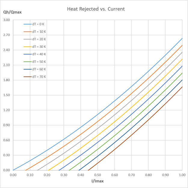
It's necessary to add some reserve when dimensioning the heat sink, to avoid that its temperature gets too high. The following diagram indicates that the heat Qh, rejected by the Peltier element, can be up to 2.6 times Qmax. This is due to the internally produced heat in the Peltier element during heat pumping. Therefore, the total heat to be dissipated at the heat sink consists of the heat of the object and the internally produced heat in the Peltier element.
The graph below shows the relationship between the heat rejected by the Peltier element versus current for different dT. Use the graphs provided by the Peltier element's manufacturer to estimate the heat to be dissipated by the heat sink.
Because the heat sink must fit into the application by its form and dimensions, the efficiency of the TEC controller plays also a crucial role, since the size of the heat sink is in relation to it. Depending on your requirements a custom-made heat sink or heat pipe might be a solution.
The thermal resistance is calculated by: RthHS = ΔTHS / Qh [K/W]
ΔTHS = Temperature difference between the heat sink and the ambient air temperature [K]
Qh = Total heat load (object + Peltier element loss) [W]
To estimate ΔTHS consider the maximum possible ambient temperature, such that your calculation holds in that case.
Dependency of Rejected Heat on dT
The following plot shows the ratio between Qh and QC for different dT. The ratio rises exponentially for every increase of dT. This means that for large dT, a large amount of heat is dissipated by the heat sink for a comparatively low amount of heat absorbed at the cold side of the Peltier element.

We can also use this plot to estimate the resulting heat sink based on the amount of heat transported QC, even before choosing a Peltier element.
To calculate the thermal resistance, we assume a realistic value for dTHS. Since we don’t know the real Qh yet, we estimate it by the above graph.
Find the ratio Qh/QC at a given current and dT.
Choose a desired temperature difference between the heat sink and the ambient air temperature ΔTHS.
Now we can replace in the above formula for RthHS Qh by our ratio Qh/QC.
RthHS = ΔTHS / (ratio*QC)
Of course, the dimensioning only holds if we later operate the Peltier element at the chosen operating point (i.e. the chosen current).
With the choice of the thermal resistance of the heat sink, dT = Tamb + ΔTHS - TO can be influenced.
(ΔTHS = Qh/RthHS)
Distributors / Manufacturers
- Digikey
- Fischer Elektronik Heat Sinks
6. Fan
Fan cooling of the heat sink reduces the thermal resistance from the heat sink to the surrounding air.
Therefore, the fan increases the thermal performance. This reduces the temperature difference dT or allows the usage of smaller heat sinks.
The TEC controllers allow the control of up to two fans, which support the following features:
- PWM control signal input to control the fan speed. The TEC generates a 1 kHz or 25 kHz PWM signal from 0 – 100%.
- Frequency generator signal output which represents the rotation speed. The output should be an open collector output signal.
It is recommended to use a fan with the same supply voltage as the TEC controller supply voltage.
Fan Recommendations
For detailed information about the fan feature fan suggestions and optimal settings, please refer to the TEC Family User Manual chapter 6.3 (PDF).
Connecting the Fan to the TEC Controller
Refer to the TEC Controller Notes page to learn how to connect the fan.
7. Example Calculations
We calculate as an example the design parameters of a thermoelectric cooling system.
There are two thermal parameters which are necessary to select a Peltier element.
- Maximum cooling capacity Qmax
- Temperature difference dT
Estimate Heat Loads and Define Temperatures
We assume an object with a heat load of QC = 10 W to be cooled to zero degrees Celsius. (TO = 0 °C) Let's say that the room temperature is 25 °C and the heat sink temperature TS is expected at 30 °C. Thus, the temperature difference between the cold side and the hot side of the Peltier element dT is 30 K. It’s important to remember that it would be incorrect to calculate dT as difference between ambient air temperature and desired object temperature.
Choosing a Peltier/ TEM Module
Our goal is to find a Qmax that is large enough to cover the needed QC and yields the best COP.
In the performance vs. current graph we locate the maximum of the dT = 30 K curve at a current of I/Imax = 0.45. In general, this ratio should not be higher than 0.7.

Using that factor for the current we find in the heat pumped vs. current graph the value QC/Qmax = 0.25 for the given temperature difference dT = 30 K and relative current of 0.45.

Now we can calculate the Qmax for the Peltier element. Qmax = QC / 0.25 = 10 W / 0.25 = 40 W
In the performance vs. current graph we find COP = 0.6 for our previously read out I/Imax. This allows us to calculate Pel = QC / COP = 10 W / 0.6 = 16.7 W.
Peltier element manufacturers offer a wide range of elements. In their product line we look for an element with a Qmax of 40 W. As we have a temperature difference of dT = 30 K, a single stage Peltier element is sufficient.
As an example, we choose a Peltier element with Qmax=41 W, dTmax=68 K, Imax=5 A and Vmax=15.4 V.
The operating current and voltage are calculated as follows:
I = Imax * (I/Imax) = 5 A * 0.45 = 2.25 A
V = Pel / I = 16.7 W / 3.83A = 7.42 V
Choosing a TEC Controller
Based on the calculated values, we choose a TEC controller TEC-1091 with 4 A output current and 21 V output voltage. It's good to add some design margin by choosing a TEC controller with higher than required output current. Later, when the performance of the system is well known, another controller with less performance may be sufficient.
Heat Sink
To find a heat sink for the Peltier element, we need to know the required thermal resistance of the heat sink. In the heat rejected vs. current graph we find Qh / Qmax=0.6 for our chosen current and dT. Thus, Qh = Qmax * 0.6 = 41 W * 0.6 = 24.6 W.

Calculation of the heat sink thermal resistance:
RthHS = ΔTHS / Qh = 5 K / 24.6 W = 0.2 K/W
We need a heat sink with a thermal resistance smaller than 0.2 K/W.
The above calculations are a first estimation of the parameters for a thermoelectric cooling system. Testing of a real system and iterating through the design steps is necessary to determine optimal system parameters.
8. Temperature Sensors
Temperature sensors are used by the TEC controller to measure the objects temperature and the temperature of the heat sink.
- Temperature Sensors – suggestions for temperature sensors (NTC, Pt100, Pt1000)
Object Temperature Measurement
To be able to control the temperature of the object, you must place a temperature probe (sensor) on the object. Please note that it's important to place the sensor as near as possible to the critical point on the object where you need the desired temperature.
Because measuring the object temperature demands higher precision and a larger range, we suggest using Pt100 sensors. To be able to measure temperatures far below 0 °C, Pt100/1000 probes are needed. This because, if the temperature gets too low, NTC probes can't be used as the resistance value gets too big. The resistance value of the sensor must be smaller than the reference resistance in the TEC controller.
When using Pt100/1000 sensors, the object temperature is measured using the four-terminal sensing technique (4-wire sensing) to achieve higher precision at low resistances. For NTC measurement 2-wire technique is used.
The term 4-wire doesn't mean that a sensor with four pins is needed. Separate pairs of current-carrying and voltage-sensing electrodes are used. (More information about four-terminal sensing)
The temperature measurement range of a TEC controller depends on both the temperature sensor and the hardware configuration. Please refer to the corresponding datasheet for detailed information.
Connecting the Temperature Sensor
Refer to the TEC Controller Notes page to learn how to connect your temperature sensor.
9. Power Supply Requirements
The power supply is the power source for the TEC controller.
Depending on the chosen TEC controller you have to choose the power supply. Make sure that the power supply is able to provide the power necessary to drive the TEC controller with the Peltier element. (As a rule of thumb, you can add 10% reserve. Multiply the necessary TEC output power times 1.1.) Refer to the datasheet of the controller for information about the input to output voltage relationship.
Power Supply Recommendations
- MEAN WELL Switching Power Supplies
10. Test Your Setup
Now that you have selected the system components you set up the application and start testing and optimizing. To facilitate the assembly and initial set up using our service software please refer to our step by step TEC Controller Setup Guide.
The comprehensive service software can be downloaded and used for free.
11. Thermoelectric Cooling Assemblies
There are also universal preassembled thermoelectric cooling assemblies available, if you don't want to build a system from scratch. These modules usually contain a metal plate to mount the object, a Peltier element, a heat sink and a fan. Using such assemblies is interesting in the prototyping phase for first experiments.
Source: http://www.thermonamic.com/


